Non classé
Présentation
Toute protection quelle qu’elle soit protège le moteur uniquement lorsque celui-ci subit une action extérieure provoquant l’échauffement excessif des enroulements : moteur qui force exagérément, mauvaise ventilation, alimentation en tension anormale.Un amorçage entre enroulements fera déclencher la protection, mais n’empêchera absolument pas sa progression. En clair lorsque la protection aura sauté il est déjà trop tard pour les enroulements qui sont donc HS. Si on prend l’exemple d’un moteur qui a pris l’eau, si le différentiel ne déclenche pas immédiatement, la protection thermique ne déclenchera que lorsque le moteur aura « amorcé ».
Lorsqu’ un moteur a grillé malgré la protection c’est :
– Soit que cette protection n’était pas efficace, du à un mauvais réglage ou un avachissement de la languette de déclanchement
– Soit que ce soit un amorçage entre enroulements, mais dans tous les cas la protection doit être changée, que l’on remplace le moteur ou qu’on le fasse rebobiner.
La protection d’un moteur peut–être :
– Interne : protection thermique, sonde thermique, fusible thermique
– Externe : relai thermique, disjoncteur thermique
Protection par Thermique Interne
Le principe de fonctionnement est celui d’un bilame qui réagit en fonction de la température des enroulements, consignée par le fabricant du moteur. Celui-ci est isolé et placé à l’intérieur du moteur sur les enroulements. Cette protection est plutôt réservée aux moteurs ne dépassant pas 0,75Kw et uniquement pour les moteurs monophasés (pompes, tondeuses, etc.).
Le contact est un NF (Normalement fermé,et donc à froid laisse passer le courant). Le branchement est donc en série sur un fil secteur et le point commun des enroulements du moteur. Les contacts de cette protection thermique sont donc suffisamment dimensionnés pour laisser passer l’intensité que consomme le moteur. L’intérêt de ce montage est d’avoir une protection incorporée et de pouvoir brancher directement le moteur avec un simple interrupteur. L’inconvénient est que lorsqu’il y a surchauffe, le bilame ouvre le contact et le moteur s’arrête. Une fois le moteur refroidi le bilame se remet à sa position initiale et le moteur repart. Si l’utilisateur de l’appareil n’est pas présent (pompe par exemple) le cycle de marche/arrêt se poursuit indéfiniment jusqu’à l’avachissement ou soudage du bilame de la protection ou du claquage du moteur.
Si par chance c’est le bilame qui a claqué , il suffit de le court-circuiter et mettre une protection thermique extérieure (relai thermique ou disjoncteur).
Schéma
Exemple de câblage de protection thermique interne, le branchement des sorties de fils du stator à la plaque à bornes n’est pas standard et chaque fabricant utilise les bornes repérées suivant sa propre logique. Avant toute intervention il faut s’assurer du repérage des circuits avec un ohmmètre. Le dessin ci-dessous permet de distinguer clairement les différents circuits. L’exemple est le cas le plus courant du moteur monophasé à condensateur permanent à 3 ou 4 fils de sorties avec le sens de rotation pré configuré.
Moteur à 3 fils de sorties.
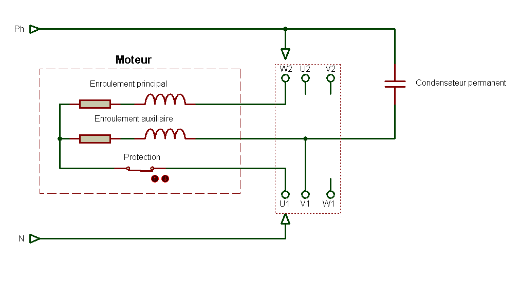
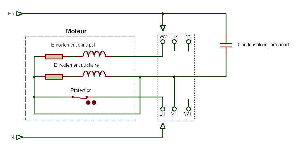
Sur le schéma électrique suivant le moteur a 4 fils de sorties, L’intérêt est de pouvoir supprimer la protection en cas de défaillance, en n’oubliant pas toutefois de mettre une protection extérieure par disjoncteur/moteur calibré.
Moteur à 4 fils de sorties..
Autre montage, si la protection est en bon état c’est de faire un montage dont la protection devient simplement une sonde thermique.
Moteur à 5 fils de sorties.

Principe de la sonde thermique (thermistance)
Protections thermiques incorporées
Les moteurs peuvent être équipés en option de sondes thermiques; ces sondes permettent de suivre l’évolution de la température aux “points chauds” afin de détecter la surcharge ou un mauvais refroidissement (ou à des points caractéristiques) pour la maintenance de l’installation.Il faut souligner qu’en aucun cas, ces sondes ne peuvent être utilisées pour réaliser une régulation directe des cycles d’utilisation des moteurs.
En contrôlant directement la température des enroulements statoriques, les relais à sondes protègent les moteurs contre les échauffements quelle qu’en soit l’origine (surcharge, élévation de la température ambiante, défaut du circuit de ventilation, fréquence de démarrage trop élevée,marche par à-coups, ……). Ce mode de protection ne peut être utilisé que si des sondes ont été incorporées aux enroulementslors de la fabrication du moteur (ou du rebobinage de celui-ci).Les relais à sondes peuvent également être utilisés pour surveiller les échauffements des organes mécaniques des moteurs ou d’autres matériels susceptibles de recevoir une sonde (paliers, circuits de graissage, radiateurs de semi-conducteurs, fluides de refroidissement, résistances de démarrage,…).
Ce système de protection contrôle la température réelle de l’élément à protéger.Il est composé:
– d’une ou plusieurs sondes à thermistances à coefficient de température positif (PTC) (composant statique dont la résistance augmente brutalement quand la température atteint un seuil prédéfini
nommé Température Nominale de Fonctionnement «TNF»). – d’un dispositif électronique qui mesure en permanence la résistance des sondes.
Un tableau ci-dessous permettant de montrer différentes sonde thermique incorporées dans le moteur
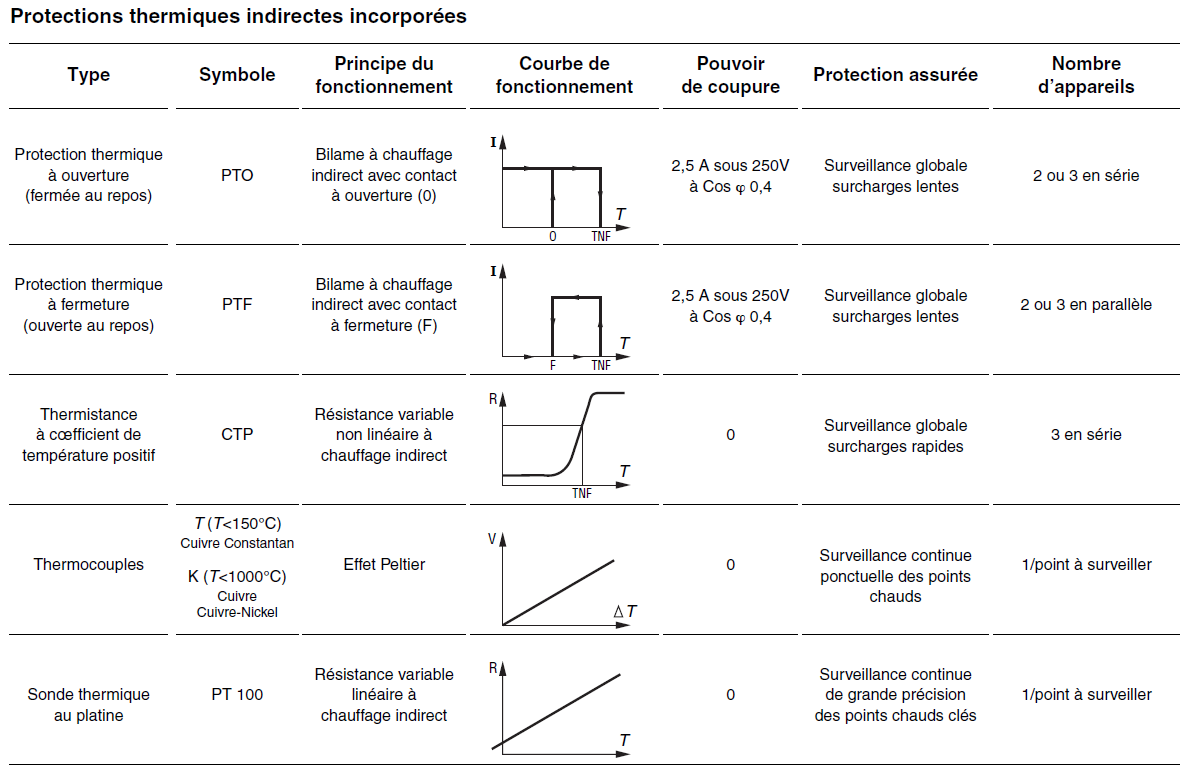
(Clique pour agrandir)
Montage des différentes protections
– PTO ou PTF, dans les circuits de commande.
– CTP, avec relais associé, dans les circuits de commande.
– PT 100 ou Thermocouples, avec appareil de lecture associé (ou enregistreur), dans les tableaux de contrôle des installations pour suivi en continu.
Lorsque le moteur comporte des accessoires (protection thermique ou résistance de réchauffage), ceux-ci sont raccordés sur des dominos à vis ou des planchettes par des fils repérés
Fonctionnement de la sonde thermique
Ce sont des résistances dont la valeur ohmique varie avec la température. En principe, ces dispositifs ne sont pas utilisés seuls, ils doublent les relais utilisant le courant absorbé comme moyen de mesure, mais la surcharge due à l’échauffement d’un palier est, en principe, insuffisante pour être détectée par les relais de surcharge, d’Où la nécessité d’intégrer une sonde thermique.
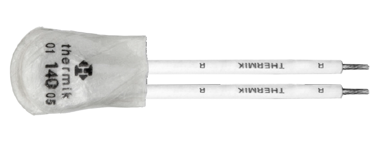
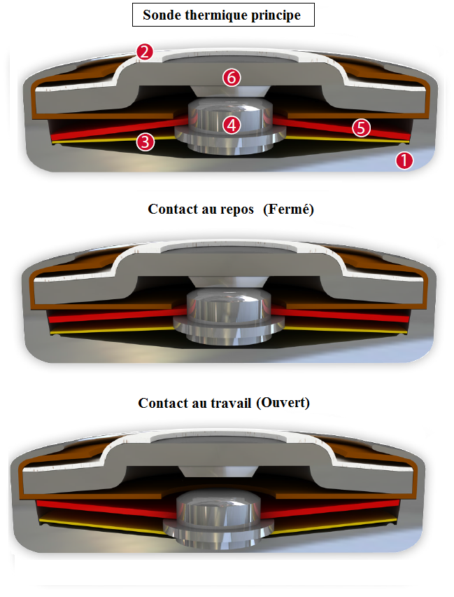
L’appareillage est constitué d’un d’un boîtier conducteur (1) et d’un capuchon de contact qui est constitué d’acier (2), qui celui-ci est isolée du capuchon. Un contact intégré d’argent fixe (6) qui ferme le boîtier comme une pile bouton. Il reste le disque (3) qui forme l’élément de transfert de courant qui est le contact mobile (4)
Le fonctionnement est le suivant
lorsque la température augmente le disque bimétallique(5) va se déformer en exerçant une pression de contact constante, stable. Le disque bimétallique (5) est un contact mobile qui fait monter ou descendre (4) sans se coller et sans avoir à ce souder. En tant que tel, il peut toujours travailler et réagit seulement à la température ambiante dans l’appareil à protéger. Quand la température de commutation nominale est atteinte, le disque bimétallique (5) va se mette en sa position inversée et pousse le ressort d’encliquetage disque (3) vers le bas. Ainsi le contact est brusquement ouverte et la montée du dispositif de température est est perturbée. Si la température ambiante tombe, le disque bimétallique (5) retourne dans sa position de départ , et le contact est à nouveau fermé.
Dernière mise à jour le 16/04/16
Présentation
Le programme ci-dessous permet d’afficher toutes les 100ms la position du curseur de la souris. Le timer1 permet de scruter en boucle le positionnement de la souris et d’afficher ces valeurs dans une TextBox.
Programmation en C#
using System;
using System.Collections.Generic;
using System.ComponentModel;
using System.Data;
using System.Drawing;
using System.Linq;
using System.Text;
using System.Threading.Tasks;
using System.Windows.Forms;

namespace Curseur_Souris
{
    public partial class Form1 : Form
    {
        public Form1()
        {
            InitializeComponent();
        }

        private void button1_Click(object sender, EventArgs e)
        {
            timer1.Enabled = true;
            timer1.Start(); //Active le timer1
        }

        private void button2_Click(object sender, EventArgs e)
        {
            timer1.Stop(); //Arrêt du timer1
        }

        private void timer1_Tick(object sender, EventArgs e)
        {
            // Toutes les 100ms le timer scrute en boucle la ligne de code ci-dessous
            textBox1.Text = Convert.ToString( Cursor.Position.X );
            textBox2.Text = Convert.ToString( Cursor.Position.Y);
        }
        private void textBox1_TextChanged(object sender, EventArgs e)
        {
            //Affichage de l'axe des X
        }
        private void textBox2_TextChanged(object sender, EventArgs e)
        {
            //Affichage de l'axe des Y
        }

    }
}
|
Pour l’utiliser vous pouvez ouvrir le programme (.exe) situé sur ce lien Curseur souris
Dernière mise à jour le 25/03/16
Présentation
Le programme ci-dessous, permet de déplacer n’importe quel fichier dans un dossier. Bien sûr afin que ce fichier soit déplacer il faut modifier les lignes de code proposé ci-dessous
Programme en C#
using System;
using System.Collections.Generic;
using System.ComponentModel;
using System.Data;
using System.Drawing;
using System.Linq;
using System.Text;
using System.Threading.Tasks;
using System.Windows.Forms;
using System.Threading;
using System.IO; //activer le système IO
using System.IO.Compression; // Ben activer la référence "System.IO.Compression.FileSystem"

namespace Deplacement_fichier_vers_dossier
{
    public partial class Form1 : Form
    {
        public Form1()
        {
            InitializeComponent();
        }

        private void button1_Click(object sender, EventArgs e)
        {
            string sourceFile = @"C:\Users\Benjamin\Desktop\Classeur1.xlsm"; // ficher excel "Classuer1.xlsm"  à déplacer
            string destinationFile = @"C:\Users\Benjamin\Desktop\test\Classeur1.xlsm"; // fichier mis dans le dossier "test" désiré

            // To move a file or folder to a new location:
            System.IO.File.Move(sourceFile, destinationFile); // procédure qui permet de déplacer le fichier Excel dans le dossier "test"

        }
    }
}
|
Historiques
25/03/16
– Première mise à disposition
Dernière mise à jour le 19/03/16
Présentation
La programmation qui va suivre est une amélioration de Simulation touches clavier 001 .La programmation est basé sur la Dll (« user32.dll »).
Programme en C#
using System;
using System.Collections.Generic;
using System.ComponentModel;
using System.Data;
using System.Drawing;
using System.Linq;
using System.Text;
using System.Threading.Tasks;
using System.Windows.Forms;
using System.Runtime.InteropServices; // on active le Runtime
using System.Threading; // permet d'utiliser le Thread.Sleep(ms)
using System.Diagnostics; // on active pour permettre d'utiliser la fonction Process.Start pour ouvrir application

namespace Touches_Clavier_002
{
    public partial class Form1 : Form
    {

        public Form1()
        {
            InitializeComponent();
        }


        private void BlocNote_Click(object sender, EventArgs e)
        {
            Process.Start(@"C:\Users\Julien\Desktop\test.txt"); // on ouvre le bloc note
            Thread.Sleep(1000); // 1 secs après
            SendKeys.Send("Bienvenue à tous sur mon site Electronique71.com"); // écriture dans le bloc note
            Thread.Sleep(1000); // 1 secs après
            SendKeys.Send("{ENTER}"); // simule touche ENTRER
            Thread.Sleep(1000); // 1 secs après
            SendKeys.Send("^{a}"); // simule touche CTRL a
            Thread.Sleep(1000); // 1 secs après
            SendKeys.Send("^{c}"); // simule touche CTRL c
            Thread.Sleep(1000); // 1 secs après
            SendKeys.Send("{ENTER}");
            Thread.Sleep(1000); // 1 secs après
            SendKeys.Send("{ENTER}");
            Thread.Sleep(1000); // 1 secs après
            SendKeys.Send("{ENTER}");
            Thread.Sleep(1000); // 1 secs après
            SendKeys.Send("^{v}"); // simule CTRL v
        }
    }
}
|
Dernière mise à jour le 19/03/16
Présentation
La programmation qui va suivre permet de simuler quelque touches du clavier azerty. La programmation est basé sur la Dll (« user32.dll »).
Programme en C#
using System;
using System.Collections.Generic;
using System.ComponentModel;
using System.Data;
using System.Drawing;
using System.Linq;
using System.Text;
using System.Threading.Tasks;
using System.Windows.Forms;
using System.Runtime.InteropServices; // on active le Runtime
using System.Threading; // permet d'utiliser le Thread.Sleep(ms)
using System.Diagnostics; // on active pour permettre d'utiliser la fonction Process.Start pour ouvrir application

namespace Touches_Clavier_001
{
    public partial class Form1 : Form
    {

        const int KEYEVENTF_KEYUP = 0x0002; //Evenement du relachement de la touche active
        const int VK_CONTROL = 0x11; //simuler touche CTRL
        const int VK_SHIFT = 0x10; // simuler touche SHIFT
        const int VK_RETURN = 0x0D; // simuler touche ENTRER
        const int J = 0x4A; //code de la touche J

        [DllImport("user32.dll", SetLastError = true)]
        static extern void keybd_event(byte bVk, byte bScan, int dwFlags, int dwExtraInfo);


        public Form1()
        {
            InitializeComponent();
        }


        private void BlocNote_Click(object sender, EventArgs e)
        {
            Process.Start(@"C:\Users\Julien\Desktop\test.txt"); //  on ouvre le bloc note situé sur le bureau
            Thread.Sleep(5000); // 5 secs après
            SendKeys.Send("Bienvenue à tous sur mon site DJelectro71.com"); // écriture dans le bloc note
            Thread.Sleep(5000); // 5 secs après
            // Ci-dessous écriture de "J" et "j"
            keybd_event(VK_RETURN, 0, 0, 0); // On active la touche ENTRER du clavier
            Thread.Sleep(1000); // 1 sec après
            keybd_event(VK_RETURN, 0, KEYEVENTF_KEYUP, 0); // On relache la touche ENTRER du clavier
            keybd_event(VK_SHIFT, 0, 0, 0); // On active la touche SHIFT du clavier
            Thread.Sleep(1000); // 1 sec après
            keybd_event(J, 0, 0, 0); // On active la touche "J"
            keybd_event(VK_SHIFT, J, KEYEVENTF_KEYUP, 0); // On relache la touche SHIFT et la touche J
            keybd_event(J, 0, 0, 0); // On active la touche "j" de nouveau
            Thread.Sleep(5000); // 5 secs après
            keybd_event(0, J, KEYEVENTF_KEYUP, 0); // On relache la touche "j"

        }
    }
}
|
Dernière mise à jour le 19/03/16
Présentation
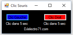
La programmation qui va suivre permet de simuler un clic gauche, ainsi que le clic droit. Vous pouvez récupérer ce petite programme à condition que vous ayez le Framework.Net d’installer sur votre ordinateur. Je vous laisse vous joindre sur ce lien Logiciels . La programmation est basé sur la Dll (“user32.dll”), et nous verrons avec le programme ci-dessous ce que C# peut faire par simulation.
Programme en C#
using System;
using System.Collections.Generic;
using System.ComponentModel;
using System.Data;
using System.Drawing;
using System.Linq;
using System.Text;
using System.Threading.Tasks;
using System.Windows.Forms;
using System.Runtime.InteropServices; // on active le Runtime
using System.Threading; // permet d'utiliser le Thread.Sleep(ms)

namespace Clic_Souris_001
{
    public partial class Form1 : Form
    {
        const uint MOUSEEVENTF_ABSOLUTE = 0x8000;
        const uint MOUSEEVENTF_LEFTDOWN = 0x0002;
        const uint MOUSEEVENTF_LEFTUP = 0x0004;
        const uint MOUSEEVENTF_MIDDLEDOWN = 0x0020;
        const uint MOUSEEVENTF_MIDDLEUP = 0x0040;
        const uint MOUSEEVENTF_MOVE = 0x0001;
        const uint MOUSEEVENTF_RIGHTDOWN = 0x0008;
        const uint MOUSEEVENTF_RIGHTUP = 0x0010;
        const uint MOUSEEVENTF_XDOWN = 0x0080;
        const uint MOUSEEVENTF_XUP = 0x0100;
        const uint MOUSEEVENTF_WHEEL = 0x0800;
        const uint MOUSEEVENTF_HWHEEL = 0x01000;

        [DllImport("user32.dll")]
        private static extern void mouse_event(uint dwFlags, uint dx, uint dy, uint dwData, int dwExtraInfo);

        public Form1()
        {
            InitializeComponent();
        }

        private void Gauche_Click(object sender, EventArgs e)
        {
            Thread.Sleep(5000); //dans 5 sec le clic
            mouse_event(MOUSEEVENTF_LEFTDOWN, 0, 0, 0, 0); // On simule le bouton gauche enfoncé
            Thread.Sleep(100); // 100 ms après
            mouse_event(MOUSEEVENTF_LEFTUP, 0, 0, 0, 0); // On simule le relâchement du bouton gauche
        }

        private void Droit_Click(object sender, EventArgs e)
        {
            Thread.Sleep(5000); //dans 5 sec le clic
            mouse_event(MOUSEEVENTF_RIGHTDOWN, 0, 0, 0, 0); // On simule le bouton droit enfoncé
            Thread.Sleep(100); // 100 ms après
            mouse_event(MOUSEEVENTF_RIGHTUP, 0, 0, 0, 0); // On simule le relâchement du bouton droit
        }
    }
}
|
Test avec le fichier (.exe) à télécharger Simulation clic souris
dernière mise à jour le 03/04/16
Présentation
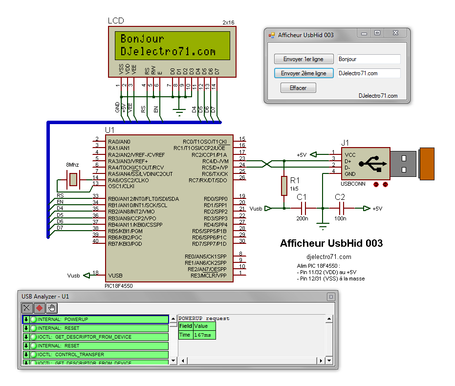
Ce nouveau montage permet d’écrire via un clavier raccorder sur le port USB d’écrire sur les deux lignes de l’afficheur LCD 2×16 caractères. je vous laisse vous plonger dans les lignes de codes situées ci-dessous
Schéma
Programme du PIC
program Afficheur_UsbHid_003;
 var
 ReadBuff: array[64] of byte; absolute 0x500;
 WriteBuff: array[64] of byte; absolute 0x500;
 i, i2:byte;
 iValueColomnLcd, iValueColomnLcd2:byte;
ConverCharByte, ConverCharByte2:byte; LCD_RS : sbit at RB0_bit; LCD_EN : sbit at RB1_bit; LCD_D4 : sbit at RB2_bit; LCD_D5 : sbit at RB3_bit; LCD_D6 : sbit at RB4_bit; LCD_D7 : sbit at RB5_bit; LCD_RS_Direction : sbit at TRISB0_bit; LCD_EN_Direction : sbit at TRISB1_bit; LCD_D4_Direction : sbit at TRISB2_bit; LCD_D5_Direction : sbit at TRISB3_bit; LCD_D6_Direction : sbit at TRISB4_bit; LCD_D7_Direction : sbit at TRISB5_bit; procedure Main_Init; begin TRISB:=%00000000; LATB:=$00; Lcd_Init; Lcd_Cmd(_LCD_CURSOR_OFF) end; procedure Interrupt; begin USB_Interrupt_Proc; end; procedure Write_LCD; begin if (HID_Read()<>0) then begin for i:=0 to 32 do //On compte de 0 à 32 pour la ligne du haut begin if (ReadBuff[i]<>0) then begin ConverCharByte:=Chr(ReadBuff[i]); Lcd_Chr(1,i,ConverCharByte); ReadBuff[i]:=0; end; begin if (ReadBuff[i]=1) then begin iValueColomnLcd:=0; Lcd_Cmd(_LCD_CLEAR); end; end; end; for i2:=32 to 63 do // On compte de 32 à 63 pour la ligne du bas begin if (ReadBuff[i2]<>0) then begin ConverCharByte2:=Chr(ReadBuff[i2]); Lcd_Chr(2,(i2-32),ConverCharByte2); ReadBuff[i2]:=0; end; begin if (ReadBuff[i2]=1) then begin iValueColomnLcd2:=0; Lcd_Cmd(_LCD_CLEAR); end; end; end; end; end; Begin Main_Init; HID_Enable(@Readbuff,@WriteBuff); While true do begin Write_LCd; end; end. |
Prototype
Pas de prototype mais le petit fichier qui va avec Afficheur UsbHid 003
Historiques
03/04/16
– Ajout schéma et modification de la console ainsi que la programmation C#
19/03/16
– Première mise à disposition
dernière mise à jour le 13/03/16
Présentation
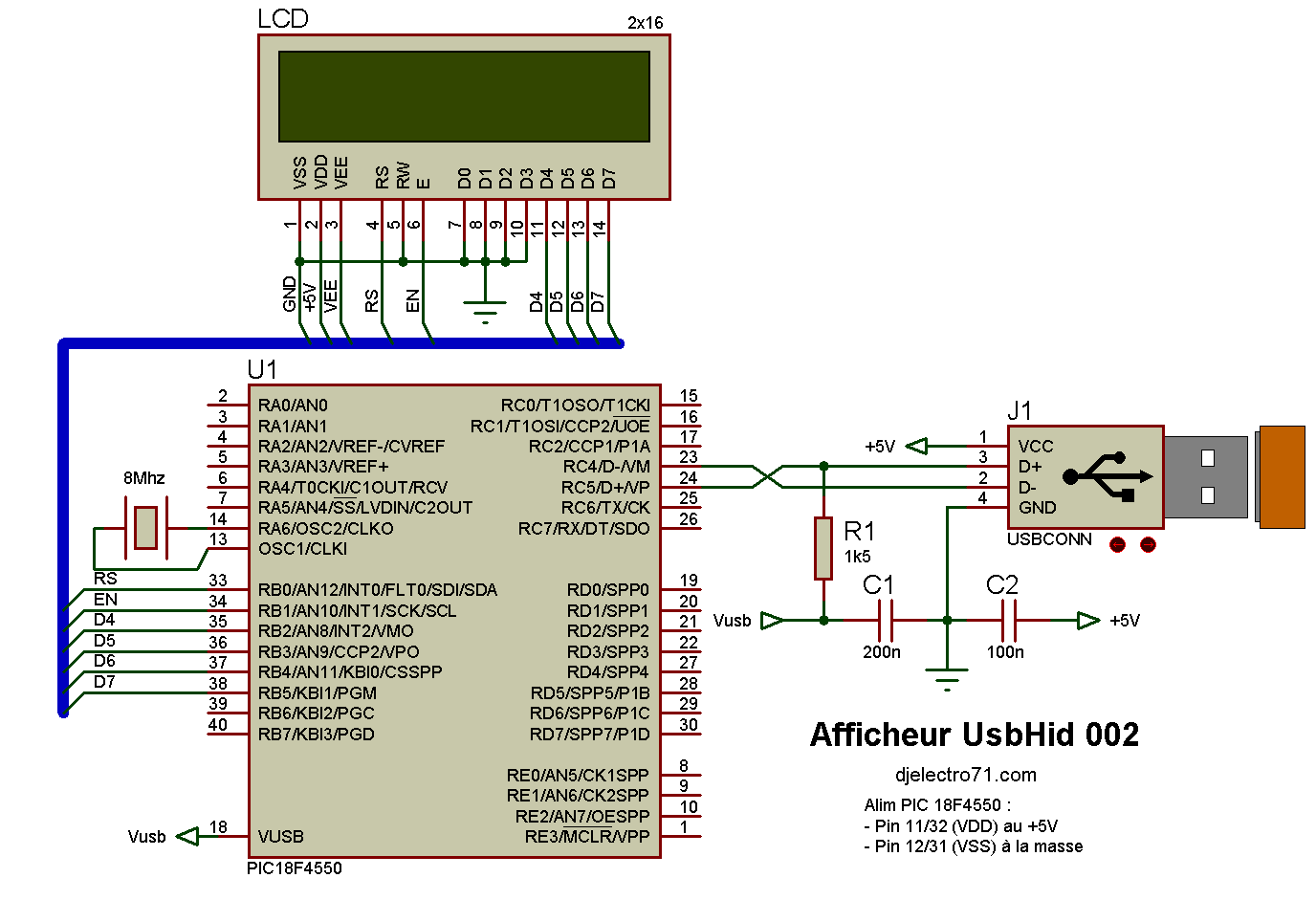
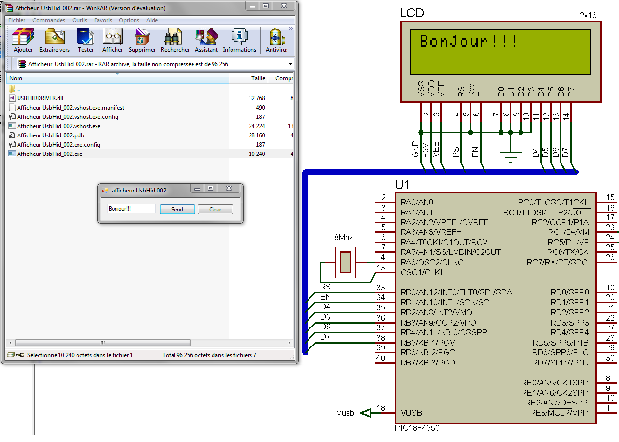
Le montage électronique présenté ci-dessous, est une amélioration de l’afficheur Afficheur UsbHid 001 qui celui-ci utilise un clavier virtuelle, alors que l’afficheur UsbHid 002 utilise le clavier uniquement. Oui! plus besoin de cliquer sur le clavier virtuelle avec la souris puisque si vous utilisé un clavier c’est encore mieux et plus rapide.
Schéma
Programmation de l’interface
Driver UsbHid
Programme du PIC
program Afficheur_UsbHid_002;
  var
  ReadBuff: array[64] of byte; absolute 0x500;
  WriteBuff: array[64] of byte; absolute 0x500;
  i:byte;
  iValueColomnLcd:byte;
  ConverCharByte:byte;
LCD_RS : sbit at RB0_bit; LCD_EN : sbit at RB1_bit; LCD_D4 : sbit at RB2_bit; LCD_D5 : sbit at RB3_bit; LCD_D6 : sbit at RB4_bit; LCD_D7 : sbit at RB5_bit; LCD_RS_Direction : sbit at TRISB0_bit; LCD_EN_Direction : sbit at TRISB1_bit; LCD_D4_Direction : sbit at TRISB2_bit; LCD_D5_Direction : sbit at TRISB3_bit; LCD_D6_Direction : sbit at TRISB4_bit; LCD_D7_Direction : sbit at TRISB5_bit; procedure Main_Init; begin TRISB:=%00000000; LATB:=$00; Lcd_Init; Lcd_Cmd(_LCD_CURSOR_OFF) end; procedure Interrupt; begin USB_Interrupt_Proc; end; procedure Write_LCD; begin if (HID_Read()<>0) then begin for i:=0 to 63 do begin if (ReadBuff[i]<>0) then begin ConverCharByte:=Chr(ReadBuff[i]); Lcd_Chr(1,i,ConverCharByte); ReadBuff[i]:=0; end; begin if (ReadBuff[i]=1) then begin iValueColomnLcd:=0; Lcd_Cmd(_LCD_CLEAR) ; end; end; end; end; end; Begin Main_Init; HID_Enable(@Readbuff,@WriteBuff); While true do begin Write_LCd; end; end. |
prototype
Aucun mais le fichier Afficheur UsbHid 002
Non testé sur platine EasyPic mais les résultats donne déjà un bon aperçu.
Historiques
13/03/16
– Première mise à disposition.
Dernière mise à jour le 13/03/16
Présentation
L’Afficheur électronique présenté dans cette article permet via une interface développé en C# sous Visual Studio d’écrire le nom de mon site “DJelectro71.com” sur un écran LCD 2×16 caractères à l’aide d’un clavier virtuelle, vous y trouverez l’exemple dans le prototype un peu plus bas qui a été entierrement développé et testé dans l’environnement MikroPascal sur platine EasyPic 7 . Le but était d’arriver à envoyer une chaine de caractères via le port USB afin que le logiciel du PIC 18F4550 puisse faire tout le travail pour décoder et d’envoyer directement les valeurs reçus sur l’afficheur LCD. Vous pourrez aborder la partie programmation un peu plus bas.
Schéma
Le schéma ci-dessous n’a rien de bien compliquer il suffit de raccorder l’écran LCD 2×16 sur les bonnes broches du PIC 18F4550.
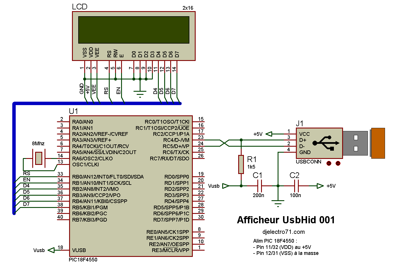
Programmation de l’interface
Pour que cela fonctionne il faut bien sûr mettre en place le driver disponible sur ce lien usbhiddriver
Programme du PIC
program Afficheur_UsbHid_001;
  var
  ReadBuff: array[64] of byte; absolute 0x500;
  WriteBuff: array[64] of byte; absolute 0x500;
  i:byte;
  iValueColomnLcd:byte;
  ConverCharByte:byte;
LCD_RS : sbit at RB0_bit; LCD_EN : sbit at RB1_bit; LCD_D4 : sbit at RB2_bit; LCD_D5 : sbit at RB3_bit; LCD_D6 : sbit at RB4_bit; LCD_D7 : sbit at RB5_bit; LCD_RS_Direction : sbit at TRISB0_bit; LCD_EN_Direction : sbit at TRISB1_bit; LCD_D4_Direction : sbit at TRISB2_bit; LCD_D5_Direction : sbit at TRISB3_bit; LCD_D6_Direction : sbit at TRISB4_bit; LCD_D7_Direction : sbit at TRISB5_bit; procedure Main_Init; begin TRISB:=%00000000; LATB:=$00; Lcd_Init; Lcd_Cmd(_LCD_CURSOR_OFF) end; procedure Interrupt; begin USB_Interrupt_Proc; end; procedure Write_LCD; begin if (HID_Read()<>0) then begin for i:=0 to 63 do begin if (ReadBuff[i]<>0) then begin ConverCharByte:=Chr(readBuff[i]); inc(iValueColomnLcd); //incrémente les conlonnes du LCD Lcd_Chr(1,iValueColomnLcd,ConverCharByte); // converti la valeur lue en un caractère begin if (ReadBuff[i]=1) then begin iValueColomnLcd:=0; Lcd_Cmd(_LCD_CLEAR) ; // on efface l'écran LCD end; end; end; end; end; end; Begin Main_Init; HID_Enable(@Readbuff,@WriteBuff); While true do begin Write_LCd; end; end. |
Prototype
Aucun, mais vous pouvez essayer l’interface Afficheur UsbHid 001, à vous de rentrer le programme en MikroPascal dans votre PIC et de créer le Vid/Pid

Juste une petite photo pour le plaisir des yeux…
Historiques
13/03/16
– Première mise à disposition
dernière mise à jour le 12/03/16
Présentation
Le programme proposé ci-dessous permet de déplacer la souris par un simple clic sur le bouton nommé “déplacement”, à vous de changer les valeurs afin que la souris se déplace à un autre endroit.
Programme en C#
using System;
using System.Collections.Generic;
using System.ComponentModel;
using System.Data;
using System.Drawing;
using System.Linq;
using System.Text;
using System.Threading.Tasks;
using System.Windows.Forms;
namespace Coordonnées_Vectorielles
{
    public partial class Form1 : Form
    {
        public Form1()
        {
            InitializeComponent();
        }
        private void button1_Click(object sender, EventArgs e)
        {
            int abscisseCurseur = Cursor.Position.X;
            int ordonneeCurseur = Cursor.Position.Y;

            Cursor.Position = new Point(524, 865); //déplacement en X=524 et Y=865
        }
    }
}
|
je vous laisse le fichier (.exe) ici
Historiques
18/01/2019
– mise à jour
12/03/2016
– 1er mise à disposition
